
Drivetrain Architecture
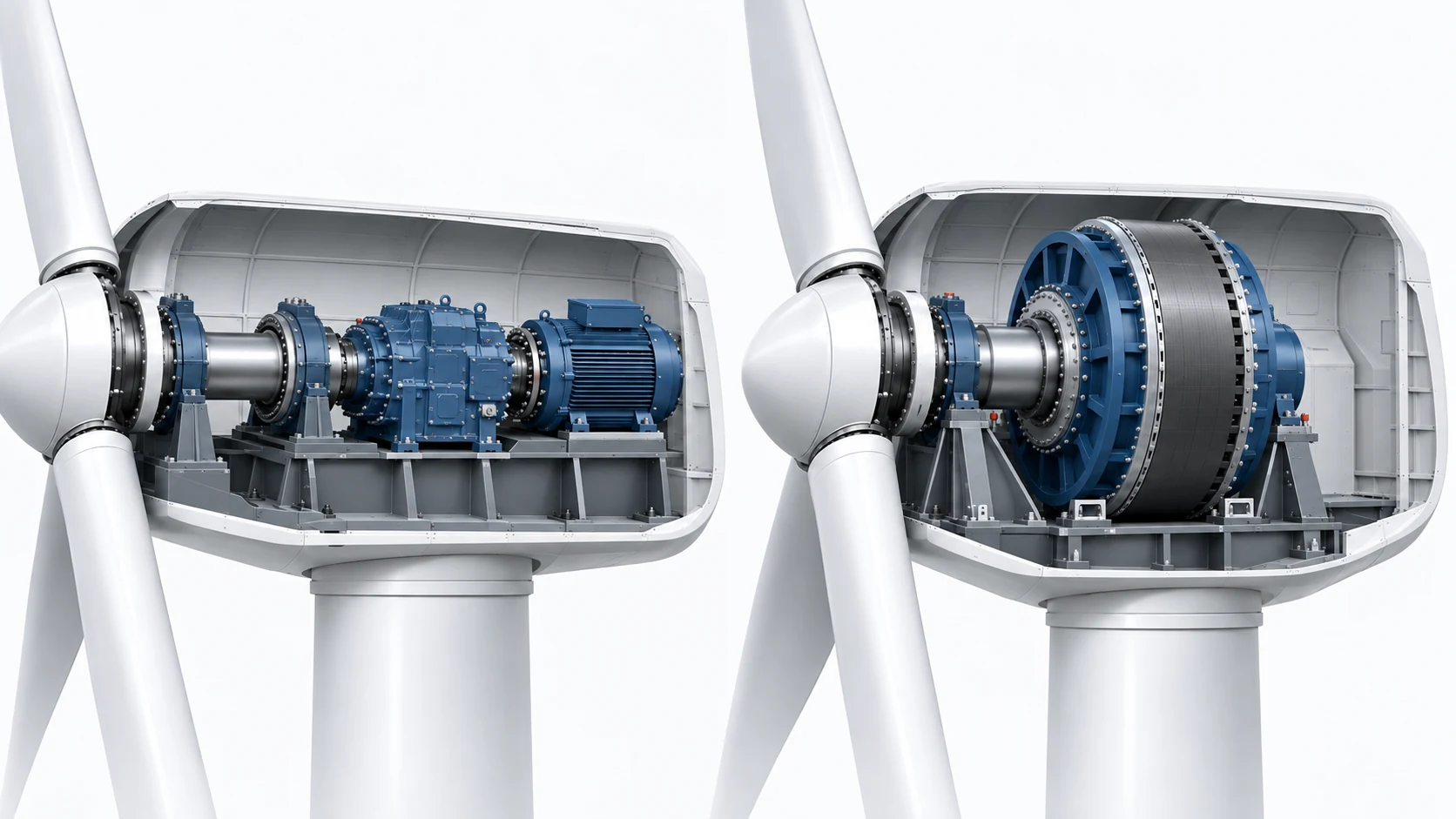
Geared · Direct Drive
Gearbox configuration and generator speed strongly affect bearing operating conditions.

WIND ENERGY
Bearing selection and application support for wind turbine main shafts, gearboxes, generators, pitch systems and yaw systems.
Request a Quote →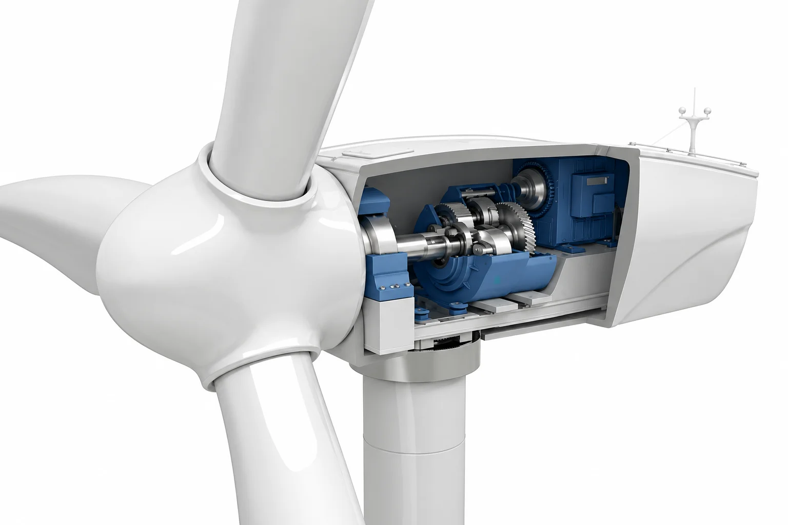
Representative geared layout. Direct-drive turbines omit the main drivetrain gearbox. Bearing arrangements vary by design; not an installation drawing.
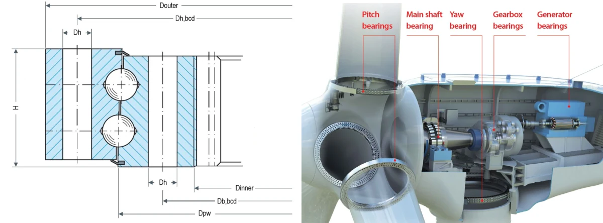
The pitch slewing bearing connects each blade root to the hub. Pitch drive bearings are separate components inside the adjustment drive.
Main shaft bearings support the low-speed rotor shaft behind the hub and ahead of the gearbox in this geared layout. Direct-drive rotor support arrangements vary by design.
Geared turbines use bearings in planetary and shaft stages to support gears and transmit loads. Direct-drive turbines have no main drivetrain gearbox.
Generator bearing speed and load depend on drivetrain architecture. In geared turbines, the generator operates at the high-speed end of the drivetrain, while direct-drive turbines operate without a gearbox.
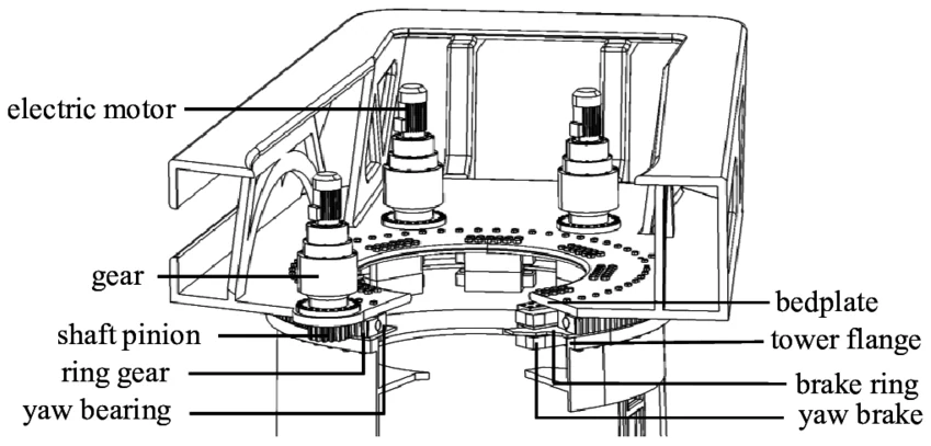
The yaw support is at the nacelle-to-tower interface. Yaw drive gearbox bearings are separate from the main support.
Bearing requirements vary by drivetrain architecture, bearing position and operating environment. Existing equipment specifications should always be verified before replacement or cross-reference.
Main shaft → Gearbox → Generator
Rotor support → Generator · No gearbox
Geared · Direct Drive
Gearbox configuration and generator speed strongly affect bearing operating conditions.
Main Shaft · Gearbox · Generator · Pitch · Yaw
Each position operates under different combinations of load, speed, alignment and motion.
Onshore · Offshore
Moisture, corrosion exposure, temperature and maintenance access affect bearing selection.
Bearing Number · Turbine Model · Drawing · BOM / Datasheet
Existing equipment information is the starting point for replacement and cross-reference.
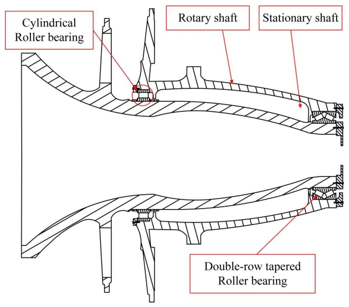
Rotor support under variable loads. Radial and axial loads, bending moment, low rotational speed and possible misalignment must be reviewed together.
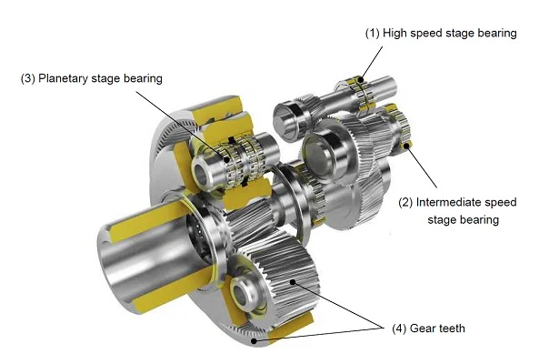
The gearbox is the most bearing-dense part of the drivetrain. Speed and load direction change from stage to stage, so each position has to be reviewed separately rather than treated as one gearbox requirement.
| Position | Operating Conditions | Typical Bearing Types | Selection Focus |
|---|---|---|---|
| Planet Carrier | Low speed; design-dependent radial and axial loads, carrier deflection and structural deformation | TRB / CRB / SRB | Stiffness / carrier deflection / fit / axial location / load distribution |
| Planet Gears | High load / compact space | CRB / TRB | Load capacity / available space |
| Low-Speed Shaft | High load / low speed | SRB / CRB / TRB | Axial location / fit / lubricant film |
| Intermediate-Speed Shaft | Rising speed / combined load | CRB / TRB / four-point contact | Speed / axial positioning |
| High-Speed Shaft | High rotational speed | CRB / TRB / ball bearings | Speed / heat / lubrication |
Typical families depend on gearbox architecture. TRB = tapered roller; CRB = cylindrical roller; SRB = spherical roller.
Four-point contact configurations require the original internal design and equipment reference; do not infer them from a broad ball-bearing category.
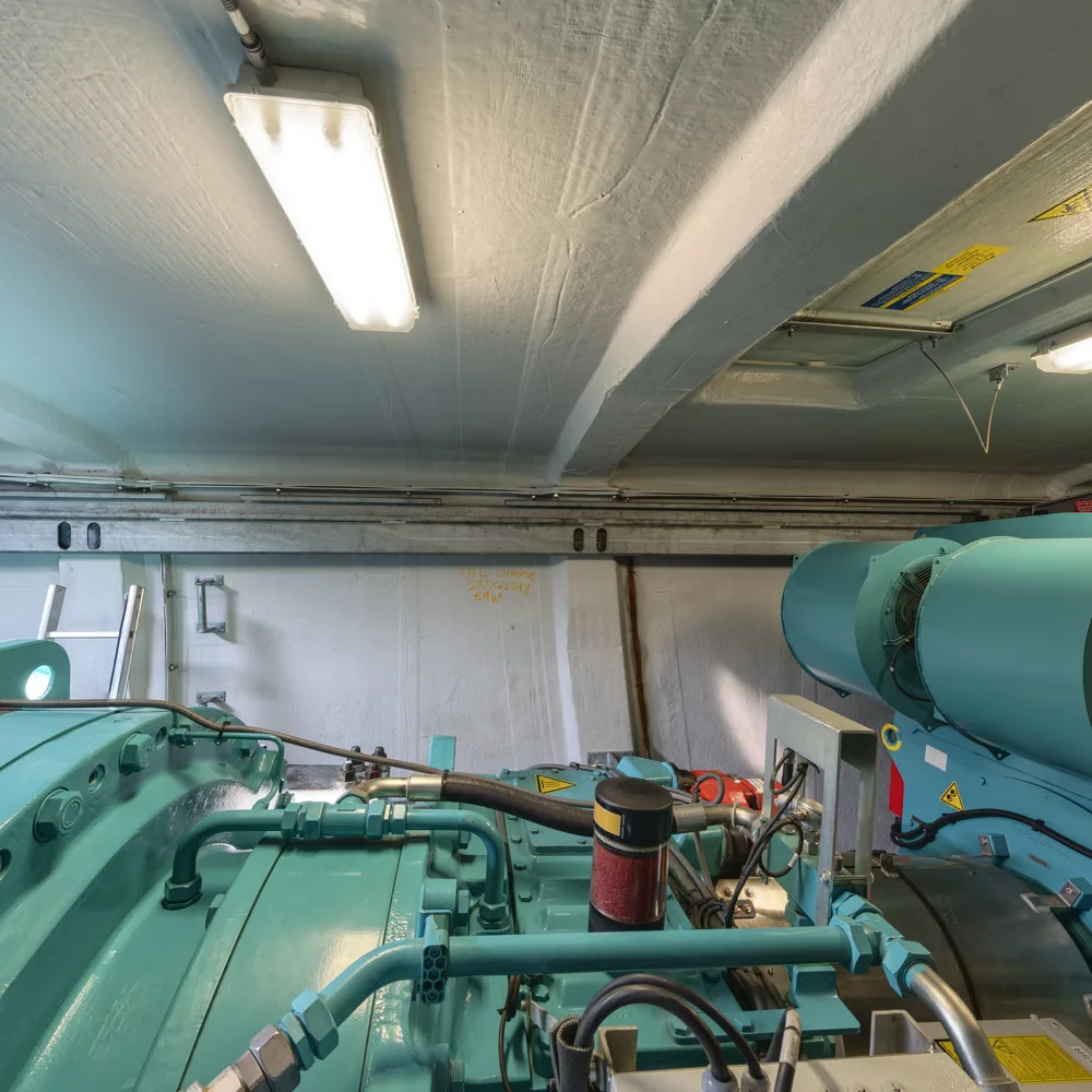
Generator rotor support in geared or direct-drive architectures. Higher rotational speed, vibration, temperature, lubrication and electrical current may govern the requirement; speed depends on turbine architecture.
Pitch slewing bearings support the blade root at the hub, while pitch drive bearings operate inside the separate adjustment gearbox.
Yaw support carries the nacelle at the tower interface; yaw drive bearings operate inside separate drive gearboxes. Some turbine designs use sliding yaw supports instead of a rolling slewing bearing.
| Application | Load | Speed | Misalignment | Environment | Typical Bearing Type | Main Selection Focus |
|---|---|---|---|---|---|---|
| Main Shaft | Radial / axial / bending moment | Very low | High | Exposed, wide temperature range | Spherical roller, tapered roller, toroidal | Load capacity at low speed and misalignment tolerance |
| Planet Carrier | Design-dependent radial / axial; carrier deflection and structural deformation | Low | Architecture dependent | Inside gearbox, oil lubricated | Spherical roller, tapered roller, cylindrical roller | Stiffness / deflection / fit / axial location / load distribution |
| Planet Gear | High radial / cyclic load | Stage-dependent relative speed | Low | Inside gearbox, oil lubricated | Cylindrical roller, needle roller, tapered roller | Lubricant film under oscillation |
| Low-Speed Shaft | High radial / axial | Low | Design dependent | Gearbox oil / temperature | SRB / CRB / TRB | Axial location / fit / lubrication |
| Intermediate Shaft | Moderate radial and axial | Moderate | Low | Inside gearbox, oil lubricated | Tapered roller, cylindrical roller, deep groove ball | Clearance, preload and mesh alignment |
| High-Speed Shaft | Lower radial, some axial | High | Low | Inside gearbox, oil lubricated | Cylindrical roller, deep groove ball, angular contact | Speed capability, heat and lubrication |
| Generator | Moderate radial | Architecture dependent | Low | Possible electrical current / temperature | Deep groove ball, cylindrical roller, insulated variants | Electrical insulation and running clearance |
| Pitch Slewing Bearing | High static / overturning moment | Very low / oscillating | Mounting dependent | Moisture / corrosion | Four-point contact slewing / large slewing arrangements | Static capacity / raceway durability / corrosion / sealing / bolt interface / lubrication |
| Pitch Drive / Gearbox Bearings | Gearbox load / variable torque | Intermittent / reversing | Gearbox design dependent | Drive enclosure / lubricant | Deep groove ball / angular contact ball / cylindrical roller / other gearbox bearings | Gearbox load / speed / lubrication / fit / service life |
| Yaw Slewing Bearing | Structural / moment load | Slow / oscillating | Mounting dependent | Outdoor / corrosion | Large slewing bearing where specified; sliding supports also exist | Static capacity / moment load / sealing / corrosion / lubrication / mounting stiffness |
| Yaw Drive / Gearbox Bearings | Variable gearbox load / reversing torque | Intermittent | Gearbox design dependent | Drive enclosure / lubricant | Deep groove ball / angular contact ball / cylindrical roller / other gearbox arrangements | Gearbox load / speed / lubrication / fit / reliability |
Bearing family alone does not determine suitability. Final selection requires load spectrum, speed, shaft / housing design, clearance, lubrication, temperature and equipment specification.
Browse explicitly associated products where available, or send a bearing reference for application-specific bearings. Product suitability requires technical verification.
Typical bearing families
Spherical Roller Bearings / Tapered Roller Bearings
Typical bearing families
Cylindrical Roller Bearings / Tapered Roller Bearings / Spherical Roller Bearings / Needle Roller Bearings
Typical bearing families
Deep Groove Ball Bearings / Cylindrical Roller Bearings / Electrically Insulated Bearings / Hybrid Bearings
Typical bearing families
Slewing Bearings / Four-point Contact Slewing Bearings / Drive Gearbox Bearings
Wind, gusts, turbulence and braking create continuously changing load spectra and occasional peaks.
Focus: Load spectrum · shock events
Main-shaft and low-speed positions can carry high loads at speeds where lubricant-film formation is difficult.
Focus: Load capacity · lubricant film
Hub, shaft, bedplate and housing deflection can alter bearing load distribution.
Focus: Alignment · stiffness · internal clearance
Speed, temperature, load and lubricant properties together determine film formation and service interval.
Focus: Lubricant specification · quantity · relubrication
Particles, condensation and seal leakage can damage raceways and accelerate wear.
Focus: Sealing · cleanliness · housing protection
Salt, humidity and limited maintenance access increase corrosion and service-life demands.
Focus: Corrosion protection · sealing · maintenance strategy
Symptom: Premature cracking or spalling; WEC requires metallurgical identification.
Possible causes: Several interacting mechanisms are under investigation; no universal single cause should be inferred.
What to check: Lubrication history, load events, service hours and the exact bearing position.
Symptom: Fluting, grey raceways or rolling-path pitting.
Possible causes: Converter-related shaft voltage, stray current and electrical discharge can damage generator bearing raceways.
What to check: Review electrical current paths, specified insulated or hybrid bearings, grounding / shaft-current control and lubrication.
Symptom: Polished or torn surface marks in the direction of sliding.
Possible causes: Insufficient lubricant film under low speed, high load, acceleration or reversing motion.
What to check: Lubricant type and fill, speed profile, and whether the loaded ring is stationary or rotating.
Symptom: Flaking or pitting on raceways or rolling elements.
Possible causes: Repeated rolling-contact stress, inadequate lubrication film, contamination, local stress concentration or improper load distribution can initiate surface or subsurface fatigue.
What to check: Actual load spectrum, mounting condition, internal clearance and recorded service life.
Symptom: Dry lubricant, discolouration or heat marks.
Possible causes: Insufficient quantity, wrong lubricant, blocked feed channels or an extended interval.
What to check: Lubricant specification, fill quantity, relubrication interval and any change in operating temperature.
Symptom: Raceway indentations and fatigue starting at dents.
Possible causes: Particles from the gearbox, the environment or the assembly process entering the bearing.
What to check: Oil cleanliness, seal condition, housing protection and assembly cleanliness.
Symptom: Rust, pitting or rough surfaces after idle periods.
Possible causes: Moisture and salt ingress, condensation during temperature cycling and inadequate protection.
What to check: Corrosion class in the machine specification, seal material and storage or idle conditions.
Symptom: Broken, deformed or worn cage sections.
Possible causes: Poor handling, abrupt acceleration, incorrect fit, inadequate lubrication or a wrong cage material.
What to check: Cage material and design in the designation, mounting procedure and transport conditions.
These patterns guide investigation. A webpage or photograph alone cannot determine a specific failure cause; examination and operating history are required.
Record the complete designation, manufacturer and suffix string from the existing component.
Establish which drivetrain position the bearing serves and what that position requires.
Measure bore, outside diameter and width, and confirm internal design, clearance, cage and seal.
Collect speed, load direction, temperature, lubrication and environment for the position.
Line up candidate configurations against the recorded requirements before any substitution.
Confirm quantity, origin, paperwork and lead time before the order is placed.
Equivalent candidates require technical verification before replacement. Compare designation, dimensions, internal design, clearance, preload, cage, seal, precision and application requirements—not dimensions alone.
Self-aligning under high radial load at low speed.
Explore Bearings →Combined radial and axial load in a preloaded pair.
Explore Bearings →High radial capacity with controlled axial freedom.
Explore Bearings →General running duty at higher speed.
Explore Bearings →Axial load in one or both directions.
Explore Bearings →Combined axial, radial and moment load in one ring.
Request This Bearing Type →Designed to carry load along the shaft axis.
Request This Bearing Type →Insulated variants for machines with shaft voltage.
Request This Bearing Type →Pitch and yaw support rings; equipment-specific geometry required.
Request This Bearing Type →Spherical roller and tapered roller arrangements are common; other designs depend on the turbine architecture. Confirm rotor support, axial location, stiffness and lubrication against the equipment specification.
Cylindrical and tapered roller bearings are used across many stages. Spherical roller, needle and ball bearing arrangements also occur. Carrier, planet and shaft positions require separate reviews.
Variable loads, shaft deflection, inadequate lubricant film, contamination and fitting conditions can contribute. A failed part, service history and equipment data are needed to investigate a particular case.
White etching cracks are subsurface cracks associated with altered microstructure. Several interacting mechanisms are discussed, including loading, sliding, lubricant chemistry and electrical effects. There is no universal single cause; metallurgical examination is needed to establish WEC.
Shaft voltage can drive current through the rolling contacts. Electrical discharge locally damages the surfaces; repeated events may produce pitting and fluting. Review the complete electrical and grounding arrangement.
Use insulated or hybrid configurations when required by the generator or equipment specification. Review shaft grounding, converter conditions, insulation location and mounting; insulation is not a universal cure for every current path.
A cross-brand reference is a candidate, not a guaranteed interchange. Verify designation, dimensions, internal design, clearance, preload, cage, seal, precision and application requirements before replacement.
Send the complete model and suffixes, brand, turbine model, bearing position, quantity and destination. Include drawings, dimensions, operating conditions and required documentation.
The pitch slewing bearing supports the blade at its root. Pitch drive gearbox bearings support gears and shafts in the actuator. They are different components with different loads and dimensions.
The yaw support connects the nacelle to the tower and may use a slewing ring or sliding arrangement. Yaw drive bearings are inside the gear units that turn the nacelle. Identify which component is required.
Operating clearance changes with shaft and housing fits and temperature differences. Too little or too much can affect load distribution, heat and stiffness. Retain the original specification and check the arrangement before changing clearance or preload.
No. Geared and direct-drive turbines have different arrangements. Generator speed, rotor support and locating duties depend on the design; use the original machine documentation.
Send clear photographs of the bearing and markings, measured bore, outside diameter and width, plus turbine model and position. Measurements help identify candidates but do not establish the internal configuration.
REQUEST A QUOTE
Send a bearing number, photo, drawing, BOM or technical requirement. We can help identify suitable bearing options.
Hero wind-farm scene: supplied by HCT. Wind turbine bearing location cutaway: supplied by HCT for application reference. Representative layout; not an installation drawing.
Geared / direct-drive drivetrain comparison: HCT Bearings technical illustration, created for application reference. Representative architectures; not an installation drawing.
Generator nacelle photograph: Lauri Veerde / Wikimedia Commons, CC BY-SA 4.0. Resized and converted to WebP; adapted photograph remains CC BY-SA 4.0. Representative installation.
Main-shaft illustration: Machines 2023, 11, 681. Gearbox illustration: Evident / ALL NRG. Pitch illustration: Engineering Research, Fig. 2 (adapted from a Thyssenkrupp Rothe erde catalogue). Yaw illustration: Wind Energy Science 2023, 8, 277, Fig. 1 (reproduced there from Kim and Dalhoff, 2014). Resized / converted technical illustrations: authorization reported by HCT; underlying figure rights and attribution require review where not documented (NEEDS RIGHTS REVIEW). No manufacturer approval or product suitability is implied.
 SKF
 NSK
 NTN
 TIMKEN
 NACHI
 INA
 IKO
 THK
